|
MAP
Testing
 Complete
ECU reference voltage test at MAP Complete
ECU reference voltage test at MAP
 With
the MAP connected "in-circuit" With
the MAP connected "in-circuit"
 Connect
a voltmeter as follows, key on (KOEO) Connect
a voltmeter as follows, key on (KOEO)
 Red
lead to terminal "B", black lead to ground Red
lead to terminal "B", black lead to ground
 Measure
the Voltage values and compare to chart Measure
the Voltage values and compare to chart
 These
voltages will vary according the current weather conditions at your
location These
voltages will vary according the current weather conditions at your
location

IAT
and ECT Testing
 Remove
wiring harness from sensor/s Remove
wiring harness from sensor/s
 Install
"test harness" to IAT or ECT sensor Install
"test harness" to IAT or ECT sensor
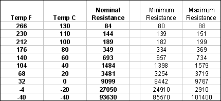
 Measure
the resistance values in Ohms and compare to chart below Measure
the resistance values in Ohms and compare to chart below

back
to top
IAT
and ECT Testing 2
 Remove
wiring harness from sensor/s Remove
wiring harness from sensor/s
 Turn
Key On (KOEO) Turn
Key On (KOEO)
 Measure
voltage between terminals "A" & "B" of the wiring harness going
to the IAT or ECT Measure
voltage between terminals "A" & "B" of the wiring harness going
to the IAT or ECT
 Black
Voltmeter lead to "B", red lead to "A" Black
Voltmeter lead to "B", red lead to "A"
 Voltage
should be 5 vDC +/- 10% (KOEO) Voltage
should be 5 vDC +/- 10% (KOEO)
back
to top
Governor
Actuator Testing
 Disconnect
wire/s to Governor Actuator Disconnect
wire/s to Governor Actuator
 Measure
the resistance of the actuator Measure
the resistance of the actuator
 3.0-4.5
Ohms is specification 3.0-4.5
Ohms is specification
 Turn
Key on and measure voltage on the harness Turn
Key on and measure voltage on the harness
 Volt
meter red lead to terminal "A", black lead to terminal "B", turn
key on (KOEO) Volt
meter red lead to terminal "A", black lead to terminal "B", turn
key on (KOEO)
 Voltage
is Pulse Width Modulated and could vary between 2.3V and 6.2V Voltage
is Pulse Width Modulated and could vary between 2.3V and 6.2V
back
to top
Fuel
Injector Testing
 Disconnect
wire/s to fuel injector Disconnect
wire/s to fuel injector
 Measure
the resistance of the fuel injector Measure
the resistance of the fuel injector
 1.2
- 1.6 Ohms is specification 1.2
- 1.6 Ohms is specification
 Turn
Key on and measure voltage on the harness Turn
Key on and measure voltage on the harness
 Volt
meter red lead to terminal "A", black lead to terminal "B", turn
key on (KOEO) Volt
meter red lead to terminal "A", black lead to terminal "B", turn
key on (KOEO)
 Voltage
is pulsing but can be seen. Noid light is best for this test. Voltage
is pulsing but can be seen. Noid light is best for this test.
 Complete
fuel injector "tap test" Complete
fuel injector "tap test"
back
to top
EGO
Testing
 Complete
EGO Bias voltage test Complete
EGO Bias voltage test
 With
the EGO connected "in-circuit" With
the EGO connected "in-circuit"
 Connect
a voltmeter as follows, key on (KOEO) Connect
a voltmeter as follows, key on (KOEO)
 Red
lead to Cavity "B", black lead to Cavity "A". Red
lead to Cavity "B", black lead to Cavity "A".
 Complete
EGO test in machine per EGO testing sequence Complete
EGO test in machine per EGO testing sequence
 'Richen
Mixture' EGO voltage 0.8 vDC or higher 'Richen
Mixture' EGO voltage 0.8 vDC or higher
 'Lean
Mixture' EGO voltage 0.3 vDC or lower 'Lean
Mixture' EGO voltage 0.3 vDC or lower
 A=
ground B= Sense C= system ground D= 12V IGN (heat) A=
ground B= Sense C= system ground D= 12V IGN (heat)
back
to top
No
Start: No Fuel, w/spark Quick Tests (Tap Test)
If the fuel pump runs or the lock off 'clicks'; operate the
fuel injector manually as follows:
 Cycle
"key" several times (off-on-off-on-off) Cycle
"key" several times (off-on-off-on-off)
 Disconnect
wiring harness to the fuel injector Disconnect
wiring harness to the fuel injector
 Connect
a voltmeter as follows, key on (KOEO) Connect
a voltmeter as follows, key on (KOEO)
 Connect
a test light to ground Connect
a test light to ground
 Tap
the other terminal of the injector with the test light probe. Tap
the other terminal of the injector with the test light probe.
 When
"tapped", the test light should light and the injector should spray
fuel When
"tapped", the test light should light and the injector should spray
fuel
back
to top
EGO
Bias Voltage Test (KOEO, Black Connector Pin 10)
 (if
equipped)oMeasure "Bias" voltage to EGO Sensor (if
equipped)oMeasure "Bias" voltage to EGO Sensor
 Turn
Key Off Turn
Key Off
 Leave
harness installed to EGO Leave
harness installed to EGO
 Start
Engine Start
Engine
 Voltmeter
red lead to Cavity "B" on EGO Sensor Connector, black lead to Cavity
"A" Voltmeter
red lead to Cavity "B" on EGO Sensor Connector, black lead to Cavity
"A"
 Results
should be 0.1 - 0.9 vDC when sensor is activated and engine running Results
should be 0.1 - 0.9 vDC when sensor is activated and engine running
back
to top
|


